Back in July of 2020 I had a Home Performance Energy Audit done on my first home. During my first summer there I noticed extremely poor AC performance. It gets to a peak of lower 100° F where I live and even if I set my thermostat to 70 all day, the temperature in my main floor will creep into the 80’s. I have had many AC professionals come look at my system, they will do a little fix or configuration and then leave me to my uncomfortable house. Of course they suggest putting in a new system (probably 20 years old), and at one point I will have to bite the bullet, but I always fear I will have some of these same root problems afterwards.
Anyway, in my pursuit of getting this under control, this audit was suggested and performed. I got the results, read them, and sat on the information for 2 years. In a nutshell it suggested re-insulating my entire home and spending 10’s of thousands of dollars. Not a very exciting thing to hear for a new home owner. Now that I have a little time and money on my hands I decided it was time to do a little DIY work. The item that most caught my eye was ventilation.
Adequate ventilation to the living area of the home is required prior to air sealing the building shell. A properly sized mechanical ventilation system must be installed prior to any shell improvement measures.
This seemed like the logical starting point, it was cheapest, and they even mentioned the specific model they had in mind. They suggested to install a Panasonic Whisper Green Bath Fan to run continuously. The idea is a high efficiency, quiet fan that runs all the time for some air exchange, that will ramp up when signaled by a switch. The more I researched this fan I found that there were a few models to choose from, and a lot of mentions of CFM (Cubic Feet per Minute) values.
The main two options are 50-80-110, or 110-130-150 CFM. This refers to the high level output of the fan. The equation for maximum output is pretty easy. You’ll want at least 50 CFM for a bathroom, and at least 1 CFM per square foot of room area for larger bathrooms above 50 sqft. Then you add in considerations for jetted tubs, separate rooms, alcoves, or non-standard ceiling heights. You may need greater CFM, or more than one fan.
Beyond that it was clear I wanted the Multi-Speed Module. This is what allows the fan to run at a continuously lower level, and then elevate to a maximum level of operation when switched. However, when I started looking into what I should set this low level speed at, the more I realized how complicated it was. Another phrase kept popping up, “ASHRAE 62.2”.
The American Society of Heating, Refrigerating and Air-Conditioning Engineers publish a standard for Ventilation and Acceptable Indoor Air Quality in Low-Rise Residential Buildings that is updated every few years (most recently 2019). In summary it will take your house size, number of occupants, airtightness, and local weather to inform your decisions on ventilation. The total ventilation requirement consists of the needs of the people, as well as the house itself.
- A person needs 7.5 CFM for breathing.
- Add up the number of Occupants. Add up the number of bedrooms, then add 1. Whichever is greater is the number of people to use for the calculation.
- A house needs 3 CFM of fresh air per 100 square feet of living space.
This leads us to the equation for whole house ventilation:
Qtot = .03Afloor + 7.5(Nbr + 1)Now let’s give a practical example (you can be as accurate or simple with your measurements as you see fit). Let’s say you have 2000 sqft of livable floor space in your Building Envelope – split over 3 floors, with 3 occupants, and 3 bedrooms. This gives us:
Qtot = .03 * 2000 + 7.5(3 + 1)This equates to 90 CFM (30 CFM for the occupants, and 60 CFM for the house itself). For my particular house I chose to exclude certain floor areas that were not conditioned, and pretty well sealed off. Use your best judgement to decide your floor space. As for occupants the number is a bit more complicated as that could change over time. I believe the calculation is primarily designed to take into account the bedrooms for new constructions. House builders have no idea how many people will be living there so they will make their best guess using the number of bedrooms, and adding one for safety. If you are installing a fan in your own home you have a better way to estimate. Just remember to include the possibility of future occupants, or better house sealing during the foreseeable lifetime of this fan. For example if we increase the number of occupants from 4 to 6 that adds 15 more CFM for a total of 105 CFM. It’s nice to be able to futureproof this fan.
Building Envelope: the separation of the interior and exterior of a building
Floor Area: All enclosed above- and below-grade finished areas suitable for year-round use. Include basements, or parts thereof, only if they are finished in a manner similar to the rest of the dwelling.
No house is sealed perfectly so some ventilation will happen naturally. They call this the Infiltration Rate. During my energy audit they performed a Blower Door Test to determine the airtightness of my house. All windows and openings to the outside are shut, and they attach a big red plastic enclosure with fan to my open front door. This ran for 5-15 minutes and they included a CFM50 value on my audit results, as well as a proposed value when the sealing was completed. CFM50 is the airflow from the blower door fan needed to create a change in building pressure of 50 pascals. That’s as far as I went into researching this. All I needed to know was it is a test for airtightness, and that I use this value to calculate the Infiltration Rate.
https://energyconservatory.com/blower-door-test-results-how-energy-auditors-measure-a-home
Here’s an easy equation for fan speed considering infiltration:
Qfan = Qtot - QinfThe required mechanical (fan) ventilation rate is equal to the total required ventilation rate (which we just calculated) minus the infiltration rate. So lets calculate this missing value next.
I believe there are a few acceptable ways to calculate this value, but I will show you what I believe to the the most popular, simplified calculation:
Qinf = .052 x wsf x S x CFM50Where wsf is Weather & Shielding Factor which we can find based on your address, S is the building height, and CFM50 is our blower door test result.
Weather & Shielding Factor is a value we’re going to search for based on our area. It can be found right inside the ASHRAE 62.2 document, or… It’s time I introduce this calculator – which is a great tool for finding Qinf and Qtot. However the information included in this article should help you better decide which values to input. https://www.redcalc.com/ashrae-62-2-2016/ Once you select “Use infiltration credit”, an area expands to help you search for your closest weather station by state and will return the wsf (mine is .5). There may be easier ways to find the station, especially if it could be in an adjacent state, but this certainly makes it quick.
Building Height (S) is a little more complicated. When first searching I found simple conversions to use. For 1 story S=1, for 1.5 story S=1.18, and for 2 story S=1.32. The redcalc simply asks for dwelling height, which they define as: Vertical distance between the lowest and highest above-grade points within the dwelling pressure boundary. It doesn’t seem to acknowledge half stories. So for final confirmation I went into the ASHRAE documentation for help and was able to define this:
S = (H/Hr)^.4Where H is the vertical distance from lowest above grade floor to highest ceiling, and Hr is reference height, 8.2 ft (2.5 m). With this we can confirm those simple conversions were correct. I’m still not clear if we should consider half stories. I am also not sure how to proceed when half of your basement is underground, and half is exposed like mine is. In the end I decided to go with a value of 1.5 because my house has that half story.
So let’s again use real values to use in these equations, or using redcalc.
| Construction | Existing |
| Dwelling unit | Attached |
| Infiltration Credit | Yes |
| Weather & Shielding Factor | .5 |
| Floor Area (ft2) | 2000 |
| Occupants | 4 |
| Stories | 1.5 |
| Dwelling Height | 12.3 |
| Leakage (CFM50) | 2400 |
Qinf = .052 x .5 x (12.3/8.2)^.4 x 2400 ≈ 73.4 CFMWhen choosing S you can simplify to number of Stories like 1.5 or divide the actual height by that given reference height (Hr). The result is a lot of infiltration because this house is not very airtight. Now to finish this off we have:
Qfan = 90 - 73.4 ≈ 16.6 CFMThe sum of all mechanical (fan) ventilation within the house should be at least 16.6 CFM. It may be split between multiple fans, but in this case we will just consider a single bath fan. It may be set at a constant rate, or an example 80 CFM fan may run for (16.6*60/80) 12.5 minutes per hour.
Fan run-time per hour = Qfan * 60 / fan capacityMany of the values we work with in these calculations may be imperfect or variable over time so it can be a good exercise to try a range of acceptable values to get a good average. Lets modify the CFM50 value to simulate a new airtight house. Resources suggest a value of 1000 may be good, although I don’t think I could ever get my house to this value.
Qinf = .052 x .5 x (12.3/8.2)^.4 x 1000 ≈ 30.6 CFM
Qfan = 90 - 30.6 ≈ 59.4 CFM
run-time = 59.4 * 60 / 80 = 44.5 min/hour
It looks like a 60-80 CFM fan would work for this application now and in the future. So no need to spring for the higher speed Whisper Green fan, especially because I do not have a large bathroom.
The most annoying thing about setting up this switched low/high fan is that I not only need power wires run to it, I also need to add two signal wires to a convenient place in my bathroom. Most likely you will use an existing fan cutout and the outlet box used to control the fan. Or you will create this yourself.
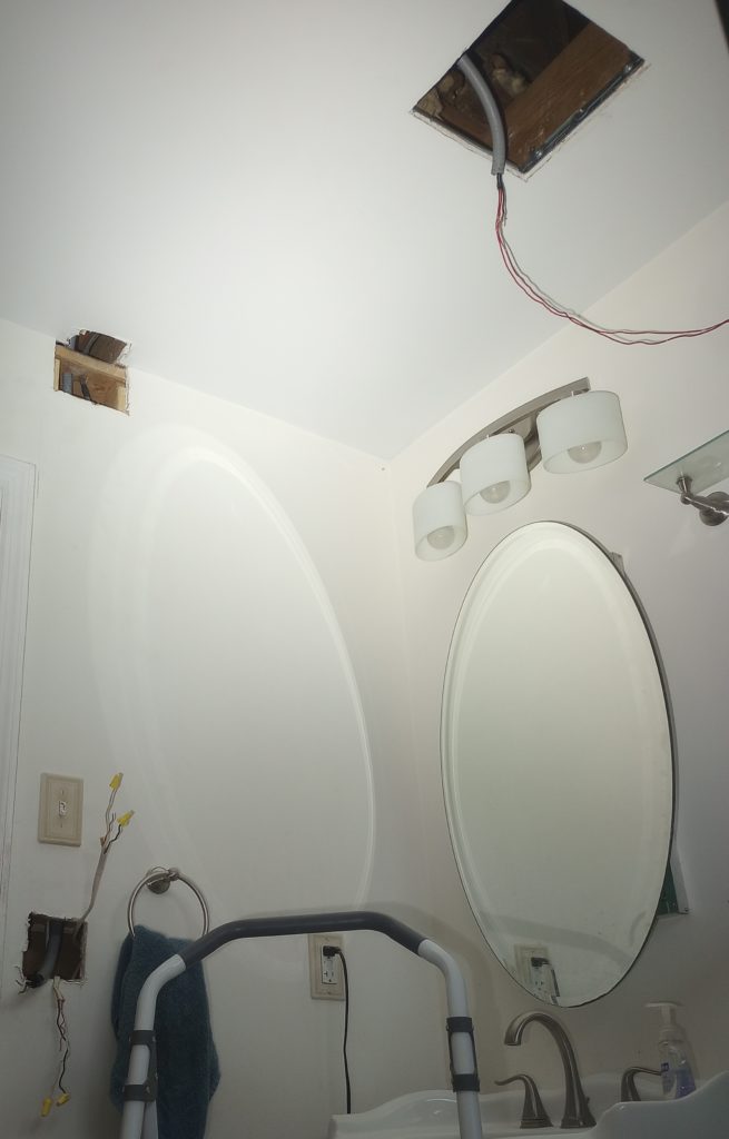
In my case, I had to pull out the old fan – which I had to do blind because I was not absolutely sure how or where it attached to the joist. Luckily the Whisper Green has a larger footprint, so no drywall patching required. Then I had to figure out how to run the signal wires from my existing switch to the fan cutout. This involved cutting the junction box out, discovering there was a fire block (horizontal stud) right above, and creating an access hole at the top of the bay. I ran the existing Romex cable along with two red THHN wires through some flexible conduit I had lying around. Then up through the switch cutout, through the two horizontal studs, and then fished the bundle over one joist bay to pull through the fan cutout. The nice thing about the conduit is I should be able to pull specific wires through without going through this whole process again.

Now wiring. It was about at this time that I noticed the Multi-Speed fan module only goes down to a minimum of 30 CFM. This means that my fan would run about twice as much as required, and that would lead to over-ventilation and over-working my AC because it would have to condition more outside air. It would seem I would have to use another piece of electronics to limit how much the fan is run per hour. Enter the AirCycler SmartExhaust Bath Fan/Light Switch. This can do all the thinking for me on a single speed fan. It can track my usage while I’m in the room, and account for any extra CFMs needed by running the fan automatically when I’m gone. I can set the Ventilation Minutes/Hour to my desired amount, set the multispeed to 0 (making it redundant), and this switch will vent my house properly.
Now at this point I’m wondering why I spent the extra money on the Multi-Speed Module because it seems useless. Most people may say oh well – go the easy route, and move on, but I will not be deterred because I am a glutton for punishment. Looking at the wire diagram – I have an idea – what if instead of using the second blue output for a light, why can’t we use it to signal the fan to enter high mode?
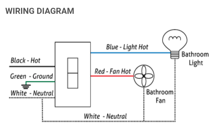
So we have 120V coming out of the blue output wire whenever the switch is set to On. I can’t just send this down the fans low-voltage signal lines (the manual explicitly warns against this). What signals the fan to go into high mode is supposed to be a normal switch – the signal wires come into contact with each other and complete the circuit. I’m sure there’s an electronic component that can turn a 120V signal into a closed switch – and there is, we use a relay.
I got most of my plan from this stackexchange solution. It provides some diagrams and even mentions a specific relay. The Air Products and Controls PAM-1 Relay Module. With a little research I found that you can supply 120V through the Black and White inputs, and that will cause a connection to be made through the Normally Open Orange and Blue outputs.
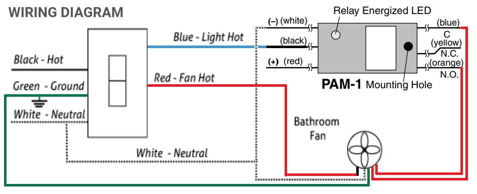
So let’s review how this would work. I set the Delay on the switch and the fan to 10 minutes. I set the switch to run 30 minutes/hour. My fan is set to high 80 CFM, and low 30 CFM. When I enter the bath and turn the switch to the On position it will send power and the high speed signal to the fan. When I leave after 5 minutes, I turn the switch to Auto and the high signal will stop, but the power will continue to run to the fan for 10 more minutes. However because I also have the delay timer set on the fan itself to 10 minutes – the fan will continue running in high mode for that duration. Assuming no other bathroom usage during that hour – the switch will automatically send power to the fan for the remaining 15 minutes of the scheduled runtime. This will be the low 30 CFM mode. Now this isn’t perfect – since I’m mixing low and high speeds the switch will not provide the perfect amount of ventilation, but this is mostly an experiment. To improve this design I would really have to make my own microcontroller to keep track of total high and low CFM timing.
Fitting these new electronics into the box was an ordeal in itself. The SmartExhaust switch is pretty chunky, plus we have the new relay and a lot more wires. The original switch cutout is between two close studs only allowing for a 2 gang (or some kind of 2.5 gang custom design) box. Luckily I had a lot of room in the stud bay – about 3.5 inches deep plus 5/8″ drywall. I used a spacious box that allowed me to bury the box farther in than the drywall line and drilled into the stud. Then I used a box extender to make up that gap. I didn’t even have to resort to trimming all the wires down because I somehow got it all to fit in that cramped space.
It works! Why did I get the toggle switch instead of the rocker style? Because I have no foresight and really wanted to shop for a non-matching face plate. But again, it works. I now have a super quiet fan – made even quieter by the fact that it’s scheduled to run at the lowest speed, and only during half of the hour. I have to admit I do miss the loud hum of my old fan when I’m doing my business.